
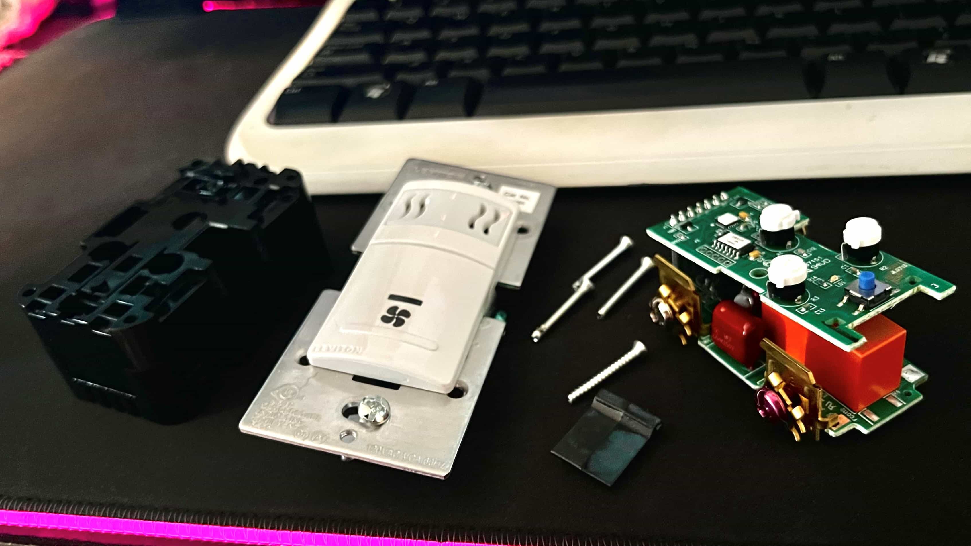
Pictured - The fully disassembled Leviton IPHS5-1LW
Introduction
DANGER! This guide involves working with high voltage AC wiring. Do not attempt to perform manual wiring on any of the circuits in your home. This guide is intended solely for educational use.
DANGER! Do not disassemble AC wiring devices as even de-energized devices may store some lethal energy in their components.
The Leviton IPHS5-1LW In-Wall Humidity Sensor & Fan Control is a neat and novel method of controlling your bathroom fan. Its built-in humidity sensor turns the fan on when humidity is sensed, and then shuts it off when ambient humidity returns to normal (e.g. when the room steams up from a hot shower). This is certainly useful as a modern convenience, as well as it is a clever energy-saving device.
As dandy as this little switch is, it’s smart, but it’s not smart smart. By smart smart, I mean internet-of-things smart. Unfortunately, this device’s automation routines are subject and limited to its own local decision-making, and cannot be externally influenced nor read from. Alas, this can be fixed:
 Pictured - Smart home device. Photo credit - Anete Lusina
With some reverse engineering and hacking, we can get this switch online and connected to our home automation server by integrating its logic with an Espressif ESP8266 Wi-Fi MCU . Once connected, we can even interface with it by using smart assistants like Alexa, Siri, and Google Home.
This guide will explain the steps I went through in reverse engineering the Leviton IPHS5-1LW and interfacing its logic with the ESP8266 chip.
Analyzing the board
The first step in reverse-engineering a circuit is to take a glance at the board and find the main logic ICs. In this case, I identified the Microchip PIC16F1823 8-bit microcontroller IC as the main logic processor used in the Leviton IPHS5-1LW switch. The PIC16F1823 will be our main target for analyzing and hacking the circuit’s logic.
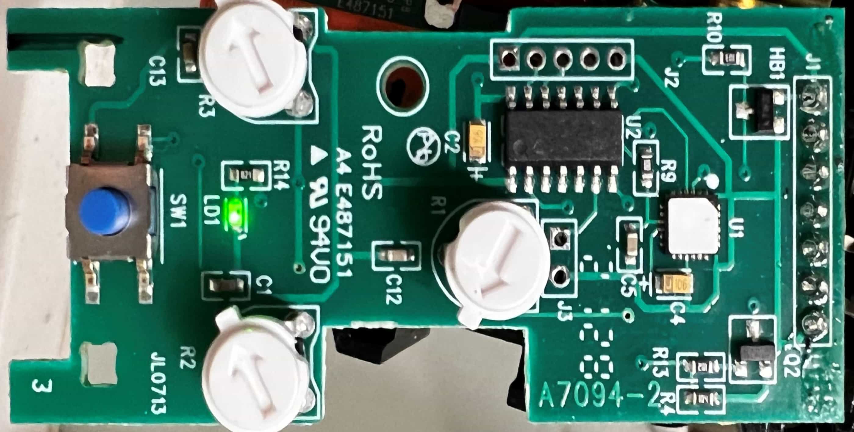 Pictured - Fig. 1: Photo of the IPHS5-1LW logic board
Pictured above (Fig. 1) is a close-up shot of the low-voltage logic board found in the Leviton IPHS5-1LW. The larger 14-pin SMT IC, in the top-right quadrant of the board, is our target: the PIC16F1823.
From this image, we can see several empty through-hole pads used as test points in the factory where the board is assembled. These can be useful as probing points, as some of these have traces leading directly to the SMT pads on the PIC15F1823.
Of course, the datasheet will tell us everything we need to know about each of the the I/O pins, as shown in the following diagram and pin allocation chart pulled from the datasheet:
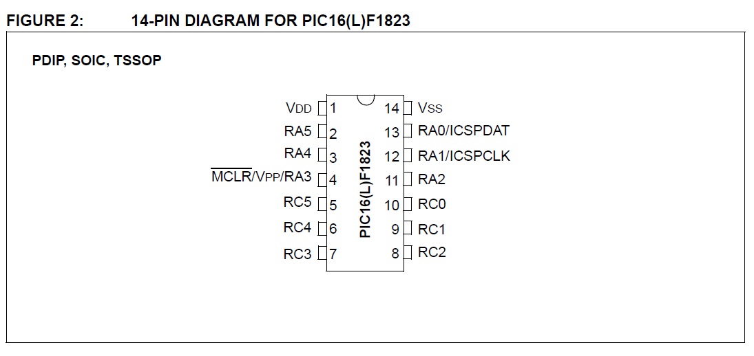 Pictured - Fig. 2: PIC16F1823 pinout
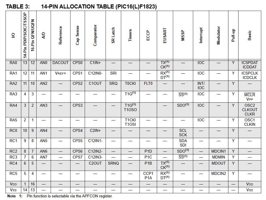 Pictured - Fig. 3: PIC16F1823 pin allocation table
This key shows us where the power pins, VSS (voltage source) and VDD (voltage drain), are located. From here, we just need to isolate the pins responsible for the logic of the fan relay driver and for the logic of the activation button. To do this, we will have to test probe the circuit while it is live.
Probing the circuit
DANGER! Exposing live high voltage AC house wiring while also exposing live disassembled AC wiring devices is extremely hazardous and possibly lethal. Do not do this.
To locate the pins that control the fan and the button, I used my digital multimeter set to DC voltage to listen for the 3.3v logic on each general-purpose I/O pin, taking note of which pin I’m on by refrencing the pinout diagram and pin allocation diagram.
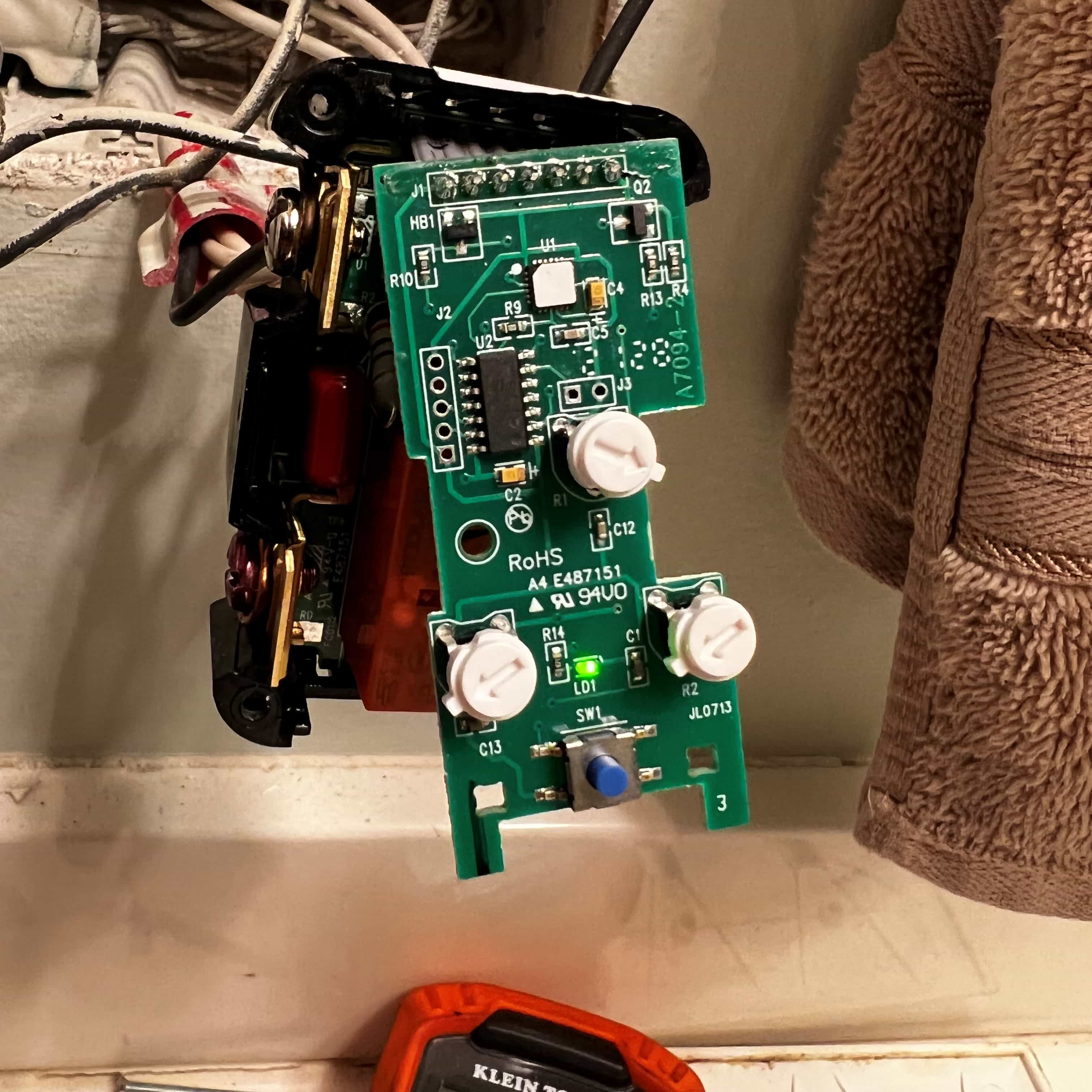 Pictured - Exposing the logic board while circuit is powered
After careful probing, I found the fan control logic output at RC5. This pin normally outputs 0.0v (LOW) while the fan is off, and outputs 3.3v (HIGH) when the fan is running. After further careful probing, I found the button logic pin at RA0. This pin normally outputs 3.3v (HIGH), and changes to 0.0v (LOW) (short to ground) when the button is closed/depressed.
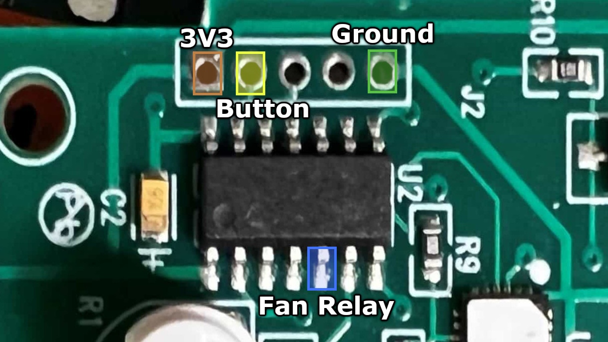 Pictured - Fig. 4: Labeled traces on the PIC16F1823 chip
With the logic found and analyzed, it’s time to move on to the next step: soldering in our mod wires.
Soldering in wires
For modularity’s sake, and to speed up testing, I opted to use a rectangular male pin header jumper ribbon cable (with one end cut off for board soldering) to connect to the logic board. These male header pins will be accessible through the side of the black plastic case that houses the logic and relay board in the IPHS5-1LW (making use of the factory cutout).
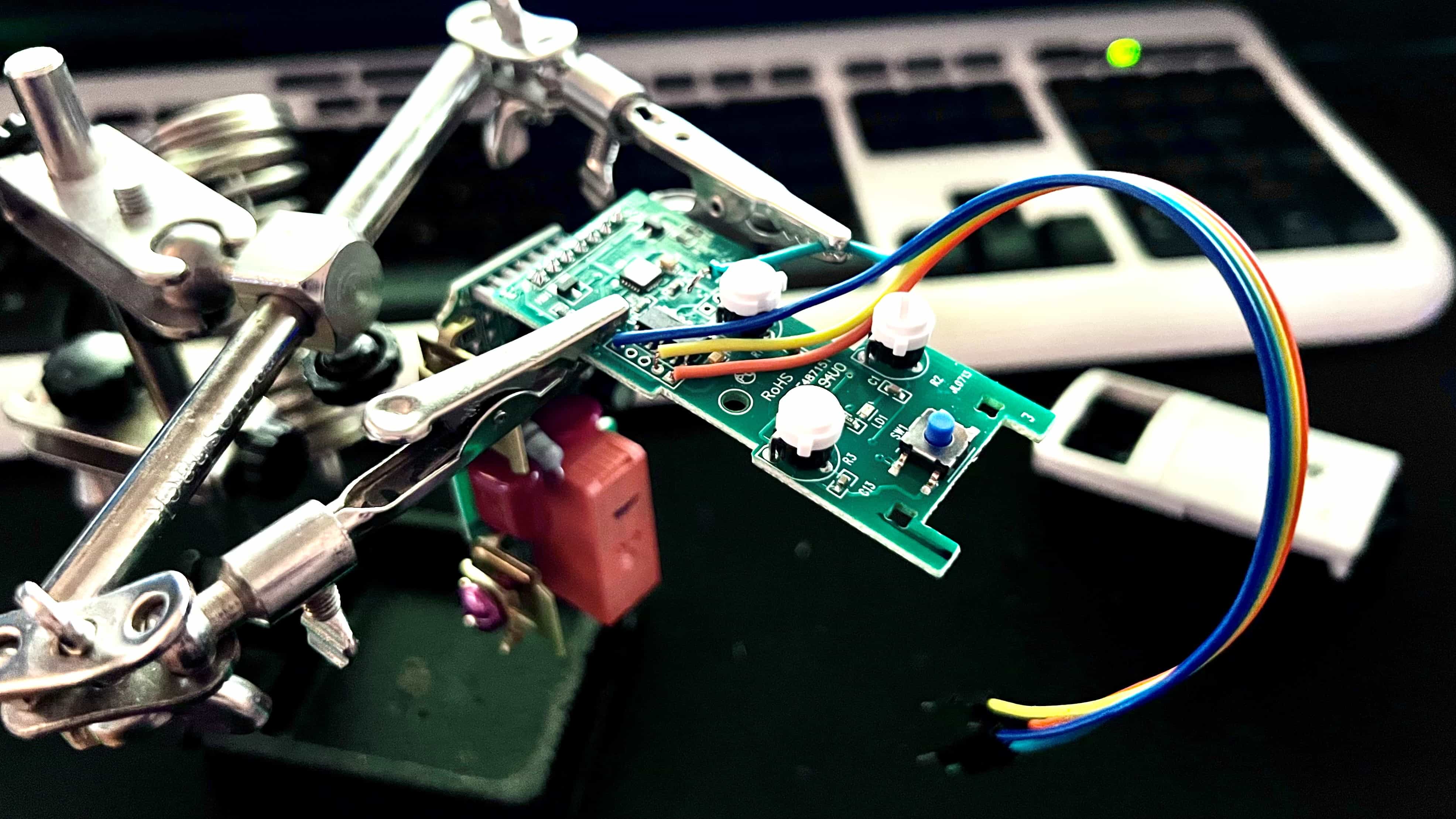 Pictured - Holding the circuit and mod wires using helping-hand clamps
After careful soldering to VSS, VDD and RA0 via the through-hole pads, as well as RC5 via direct solder to the SMT pin of the IC, our little header cable is almost ready for action. All that’s left is to carefully re-assemble the case, securing the cable tightly and taping where necessary.
Buttoning it up
Voilà— the Leviton IPHS5-1LW switch is fully re-assembled and with exposed headers to leads VSS (3v3), VDD (ground), RA0 (activation button), and RC5 (fan relay driver) from the PIC15F1823 microcontroller.
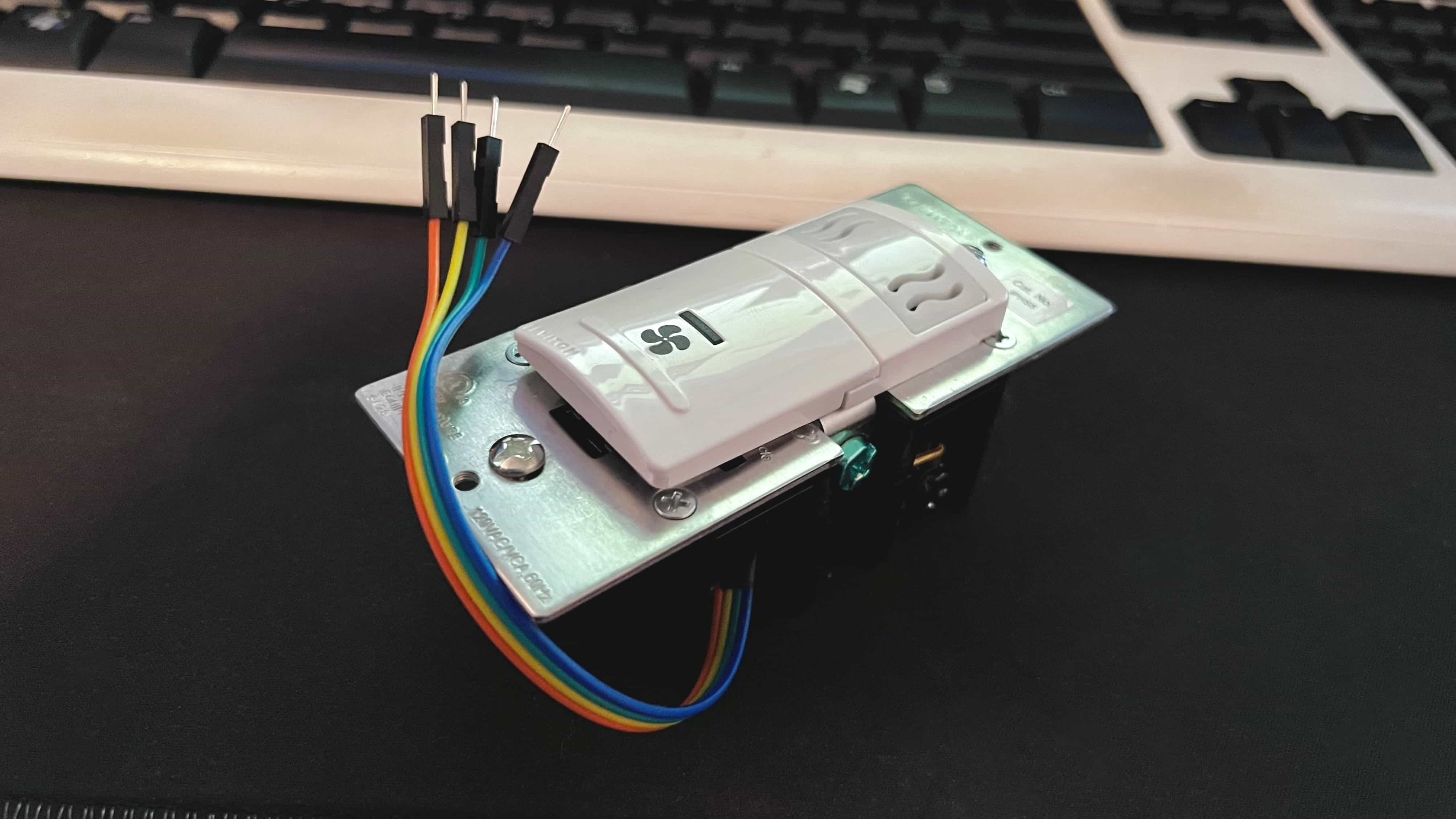 Pictured - The fully packaged IPHS5-1LW with modded signal wires added
With the relevant logic channels exposed, the next step is to use the exposed channels to interface with an Espressif ESP8266 board in order to achieve full control of the circuit via Wi-Fi.
To be continued…
As of May 2022 this project is under active development. This guide will be expanded to include ESP8266 programming and adding Wi-Fi control at some point in the future. Check back soon, or check the project’s Github page for updates.