
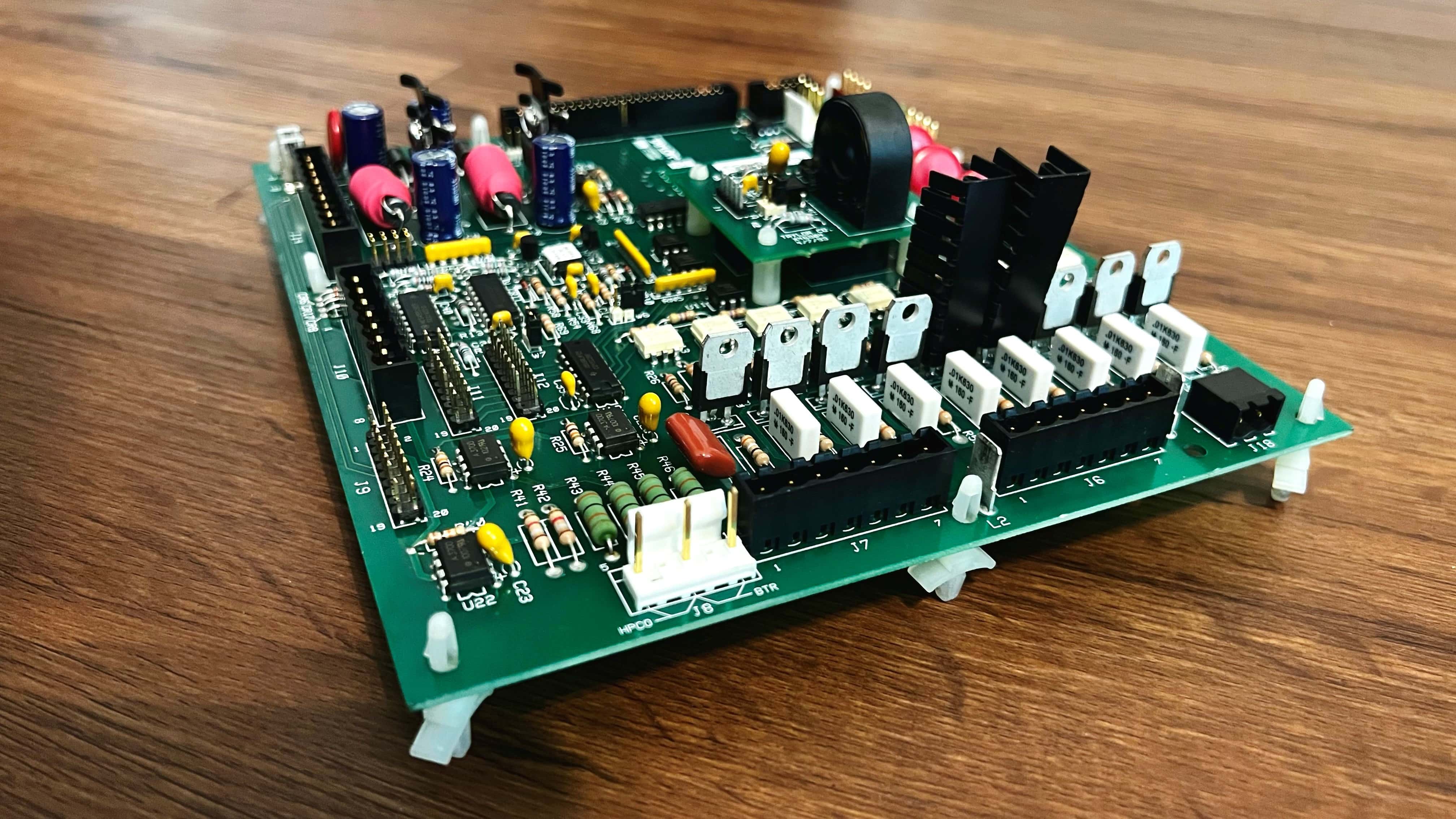
Pictured - Taylor 063926-SER “Interface Base Board”
Introducing: Headbanging
This write-up is the first in my new series I’d like to call Headbanging. To kick off the series, join me on a circuitous adventure as I dive deep down the rabbit hole of repairing a 2011 model Taylor soft serve machine (yes, the notorious, ever-faulty, engineered-to-fail brand of machines known for being broken at McYou-Know-Who’s).
In this piece, I’ll detail my one-hell-of-a fix— a true hack, involving circuit modification— that I successfully performed on a faulty C713 unit.
Without further adeiu, the story (and fix):
Erratic behavior
After a particularly stormy summer weekend in coastal Georgia, I received a Monday morning service call about a broken soft serve machine. Thunderstorms always make me nervous, and afterwards I knew I was bound to hear from somebody with (now) faulty equipment.
 Stormy weather, the bane of electrical infrastucture - Photo credit: Suparerg Suksai
Yes, some equipment was indeed faulty.
The issue: one side of the machine isn’t dispensing anything, the other side won’t shut off.
Great, I thought to myself, as I re-assured the panicked store manager everything will be fine. I have no idea what’s causing the issue or how to fix it.
Time to get digging.
Isolating the issue
To solve issues on a soft serve machine, one must think like a soft serve machine. Be the soft serve machine. Okay, maybe soft serve machines don’t have thoughts, but they do have hidden service menus: I entered my trusty access code, 5-2-3-1, and accessed the “Manual Control” screen.
Unsurprisingly, the machine did not respect my commands as I instructed it to engage the left beater motor (the beater is responsible for dispensing the product), nor would it disengage the right beater motor.
Cool, I thought, the machine has lost its mind. It must be some combination of a shorted wire and blown fuse, maybe a bad relay, or bad contactor coil.
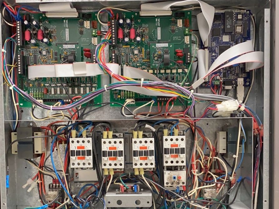 Pictured - the brains and circuitry of the C713
I popped open the access panel and began testing components. Lo and behold, everything passed. Existential dread set in.
Oh no, I thought, it’s the board. Something’s fried. In a wild ditch effort to confirm my suspicions, I transplanted a known-working interface board from an adjacent machine into the faulty machine (a maniac move). Surprise, surprise: I confirmed the issue is the interface board.
This is problematic for several reasons: it’s a proprietary part, meaning no off-the-shelf components can solve the issue. It’s expensive, and waiting to get a replacement means that many days of lost potential in revenue for the store. And there’s two fried interface boards. This is just unacceptable to me, and I knew I had to come up with something creative to get this yogurt machine operational.
Understanding the problem
To recap: we have a machine that won’t stop running the right-side beater motor, and won’t start the left-side beater motor. In other words, entirely dysfunctional. After accepting my fate, I buttoned the machine back up, condemned it by scribbling R.I.P in permanent marker on the back, and took both blown interface boards with me back to the office.
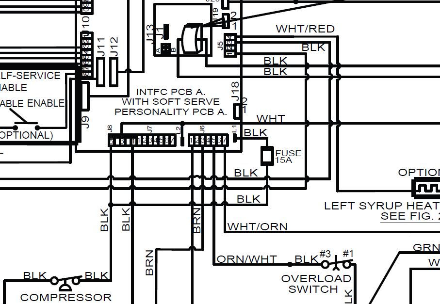 Fig. 1 - A crop of the circuit diagram for the C713
Armed with the circuit schematic (fig. 1), it didn’t take long for me to trace the output to the beater motor contactor back to pin 7 on the J6 connector. Okay, let’s look at how this pin operates:
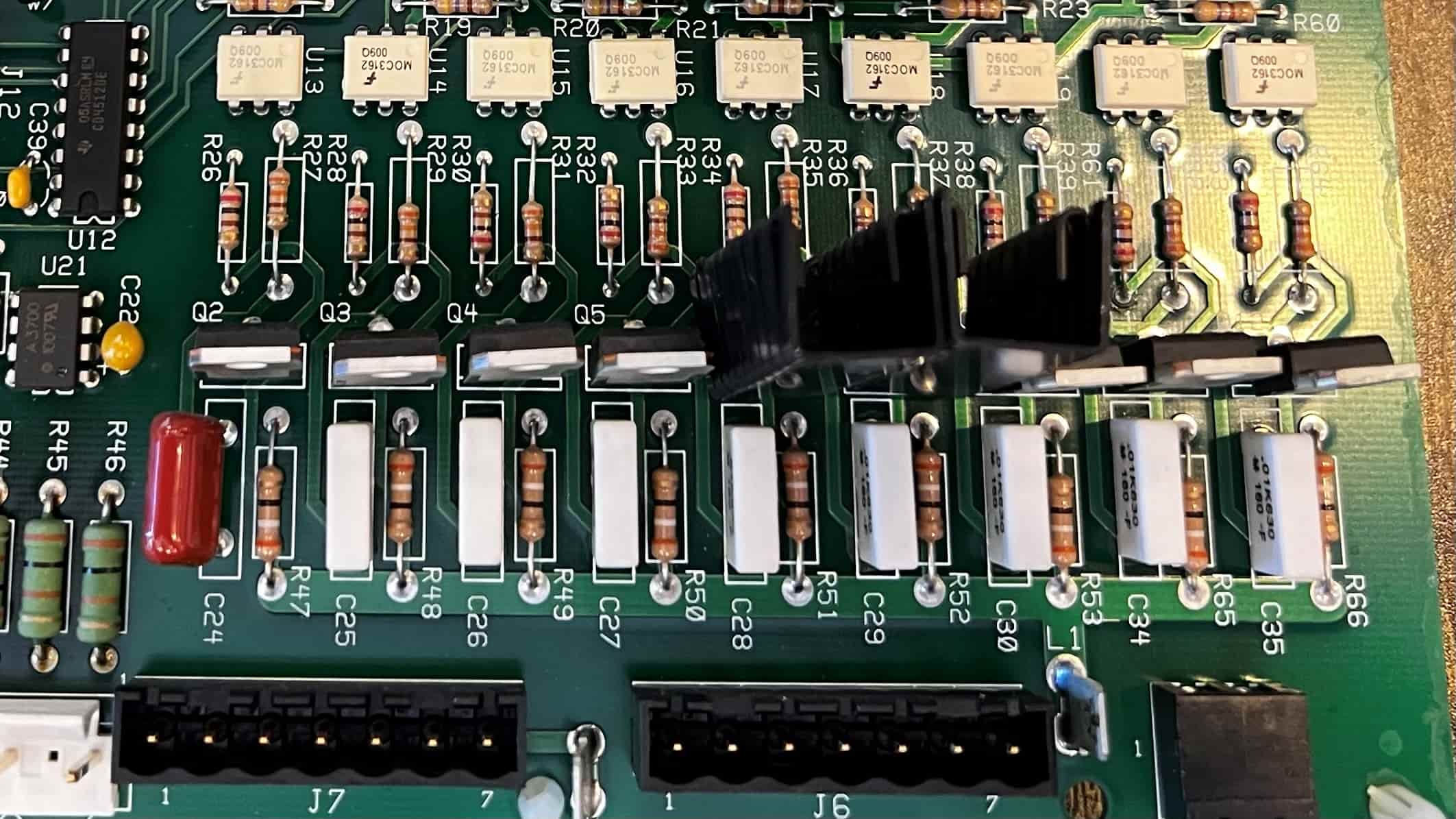 Fig. 2 - Close-up of the 063926-SER Interface Base Board
Glancing at the circuit, it’s visibly apparent that the pin is driven by a BTA16-600B triac, its output controlled by a MOC3162 optocoupler. This setup is identical for all seven pins on the J6 connector. Other outputs on this connector include condenser fan, compressor contactor, and overload switch.
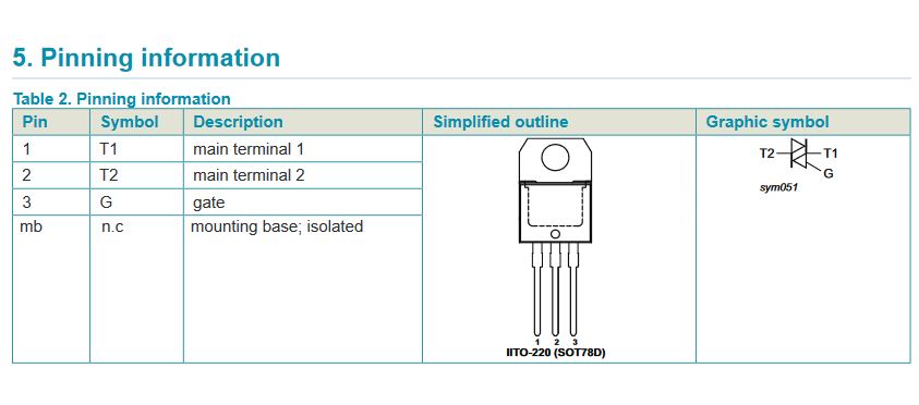 Fig. 3 - Diagram of the BTA16-600B pulled from the datasheet
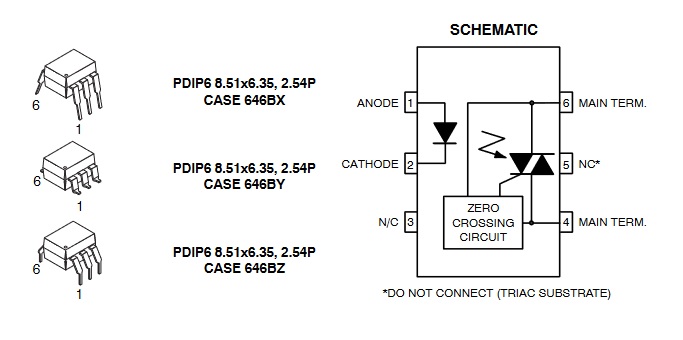 Fig. 4 - Diagram of the MOC3162 pulled from the datasheet
The obvious solution, then, would be to replace the suspicious components.
After pricing out an order, something dawned on me: there are seven of these triacs, but only four of them are populated by loads (only three are populated on the left board, as the right board solely controls the one condenser fan).
Circuit boards are typically designed with redundancy, and these boards built by Taylor are no exception. They’re meant to fit in a range of models, each with different requirements. My point is, there are untapped power outputs on this board. It hasn’t been used to its full potential (yet)!
The theorized hack
Okay, so the beater motors are controlled by motor contactors, the contactors are driven by the BTA16-600B triac, the triac is switched by the MOC3162 optocoupler, and the optocoupler is commanded by none other than the Texas Instruments ULN2803A Darlington transistor array IC.
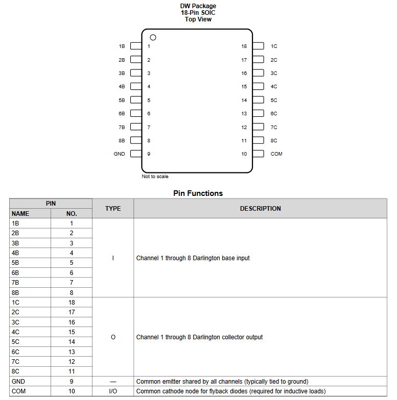 Fig. 5 - Diagram of the ULN2803A pulled from the datasheet
The plan: to re-arrange the outputs of the IC in such a way that they command the unused (presumably not fried) set of optocoupled triacs (and re-arranging the loads on the J6 connector as such). With careful solder work, this is pretty much as easy as it sounds.
For clarity, here is a diagram of how the outputs come configured on the stock circuit board:
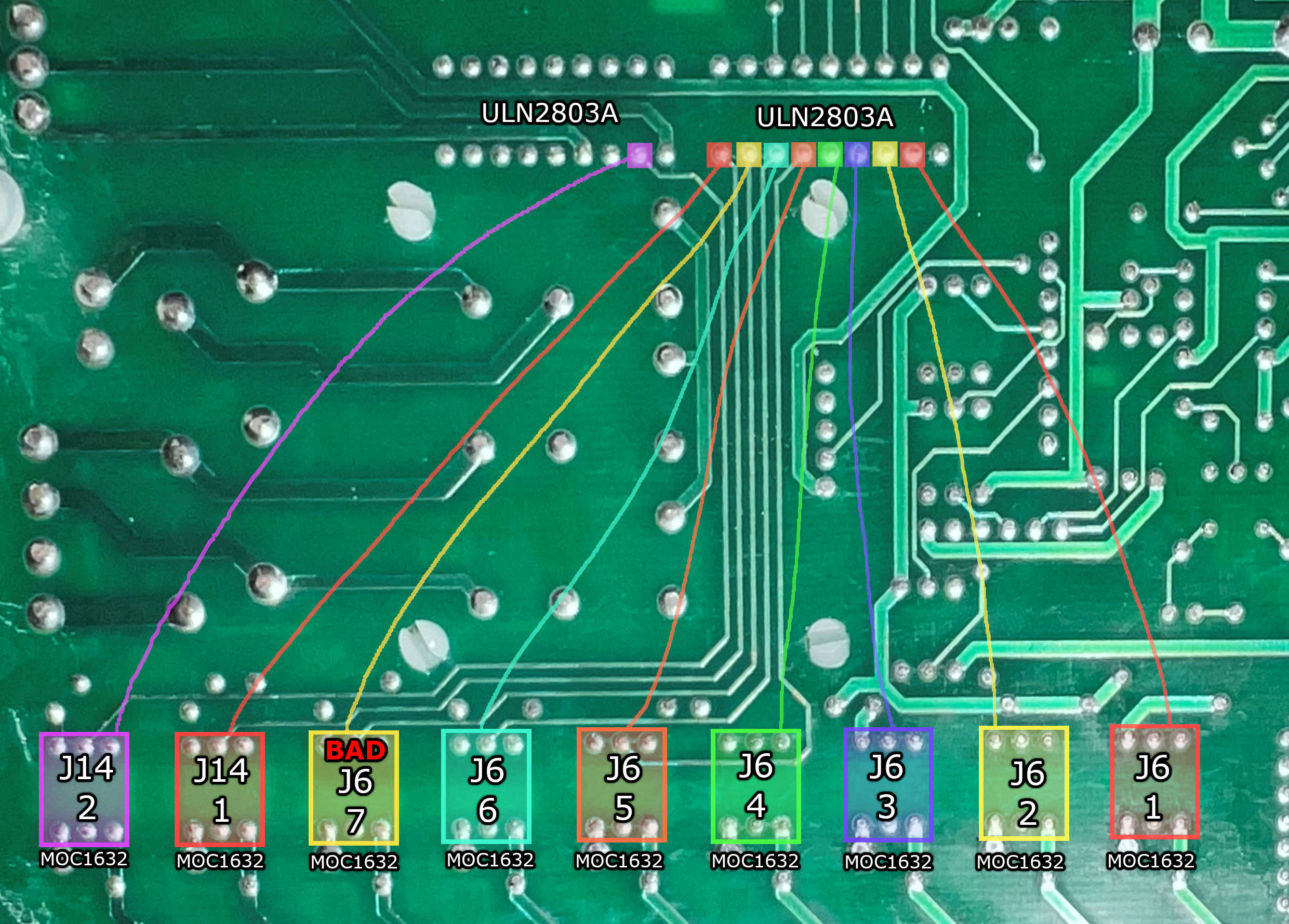 Fig. 6 - Current output configuration
And here is a diagram of the plan on re-arranging the outputs:
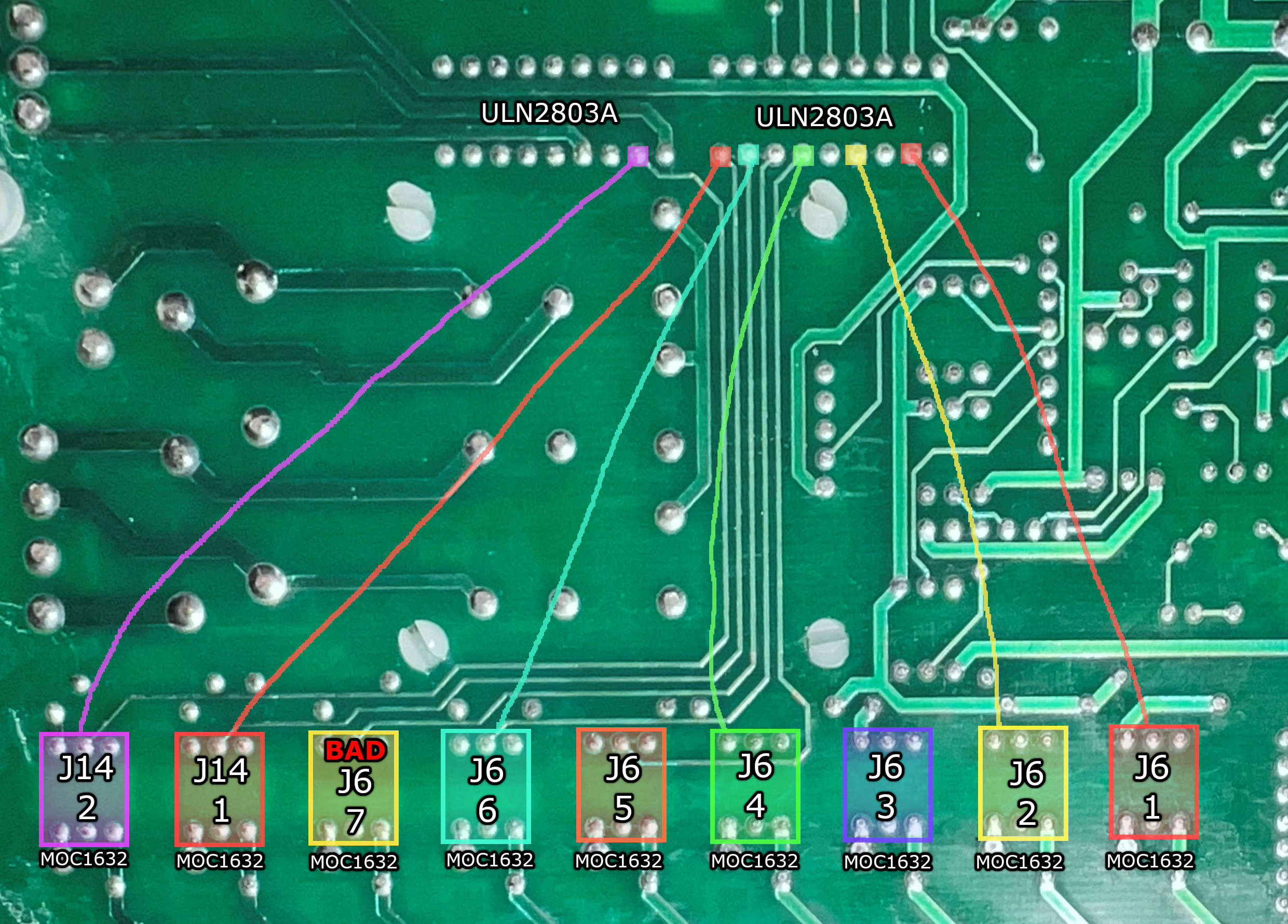 Fig. 7 - Re-arranged output configuration
The procedure
I got to work immediately. The first order of business was to sever all of the traces from the output side of the ULN20803A leading to the optocouplers. I did this carefully with a rotary hand tool, fitted with a cut-off wheel:
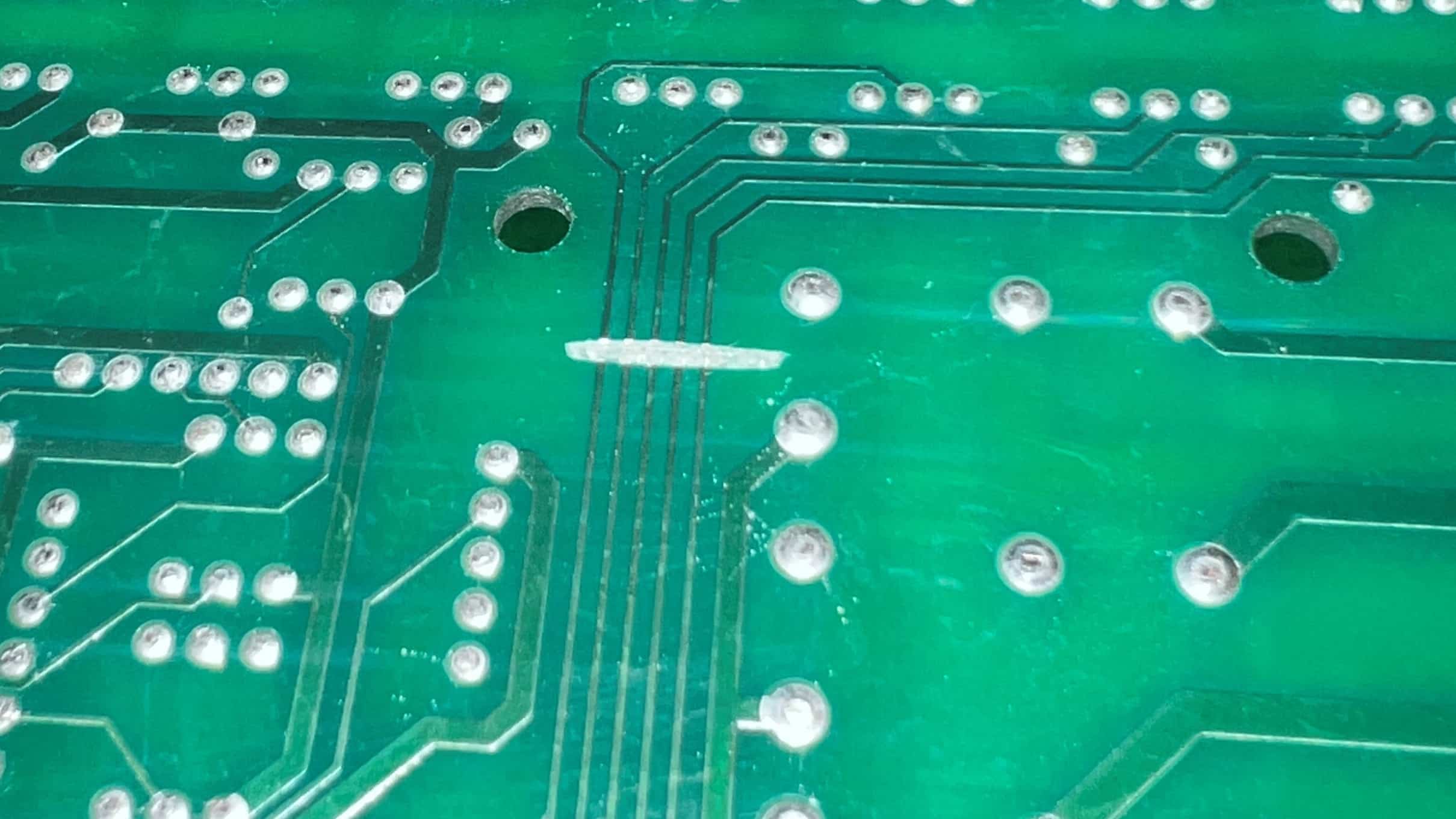 Fig. 8 - Close-up of the severed traces
With all the traces from the IC to the optocouplers severed, it’s open season to re-arrange them any which way, as long as the known-to-be-fried outputs are avoided.
I used cut-up lengths of CAT-5 strands from a junk Ethernet cord for my mod wires. Here is an image after everything was fully soldered up:
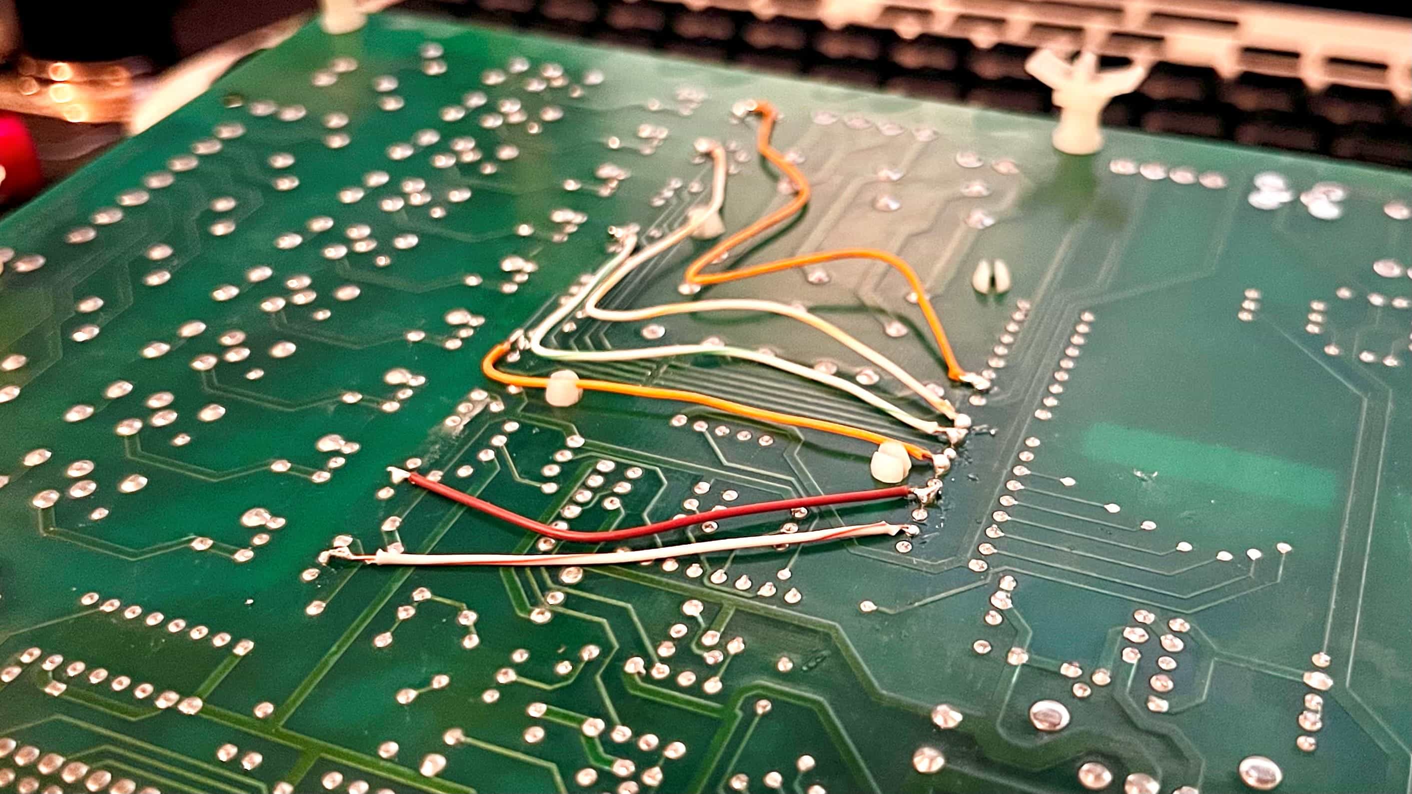 Fig. 9 - The back of the 063926-SER Interface Base Board, modded
Not pictured, I dabbed a bit of hot glue over each solder point for extra guarantee that none of the connections would be compromised or otherwise disrupted.
Also not mentioned, it was easier to destroy all the traces at once, even if some of them would be hooked back up, rather than precicely destroy the couple that I needed to in order move the power output.
And that is the fix.
Mission success
Whew. Look at that. After rewiring, both boards installed and ran perfectly. Great success! The machine dispensed delicious frozen yogurt without a problem. I filled a victory cup, as I always do (so I can “test” the machine), ceremoniously scarfed the whole thing, and ended up with brainfreeze. Regardless of frozen-dairy-inflicted cranial discomfort, I was ecstatic.
 Pictured: Delicious frozen yogurt. Photo credit - Fuse Frozen Co
We may never know what fried both those boards. I’m assuming brown-outs or other power related issues due to inclement weather.
Alas, with an understanding of circuitry, and no money spent, I was able to successfully breathe new life into these interface boards. No waiting for parts to ship, no burden placed on the company’s bottom line; a job well done.
In the process, I learned quite a bit about how the C713 functions at its board logic level. I’m sure this knowledge will come in handy again in the future.
Who knew it would be that simple? This is easily a hall-of-fame fix (for me). Please pass this write-up on if you found it interesting or helpful in any way. I can rest easy now, knowing that Taylor won’t be profiting off their own broken products again (if I’m there to do anything about it, at least)— not today.
Shout-outs and thank you to Fuse Frozen Co. for enlisting my help, and for granting permission to publish my findings in this write-up.